
Aurecon designs unique duckbill spillway for the raising of Garden Route Dam
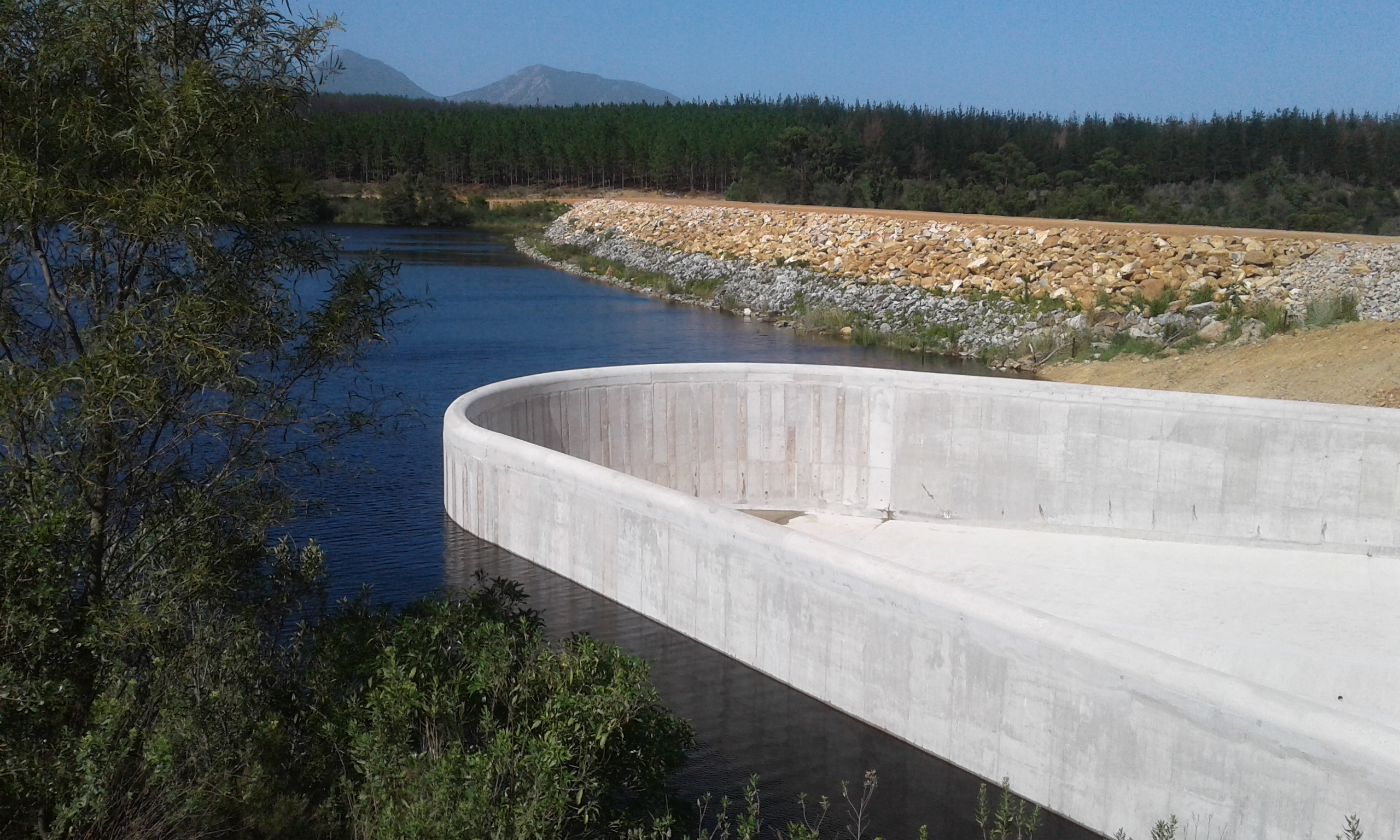
| The dam was raised by 2.5 m, due to the local terrain | 1.7 MB | Download | |
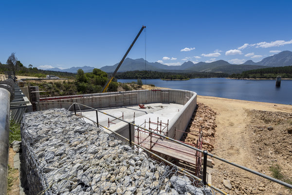
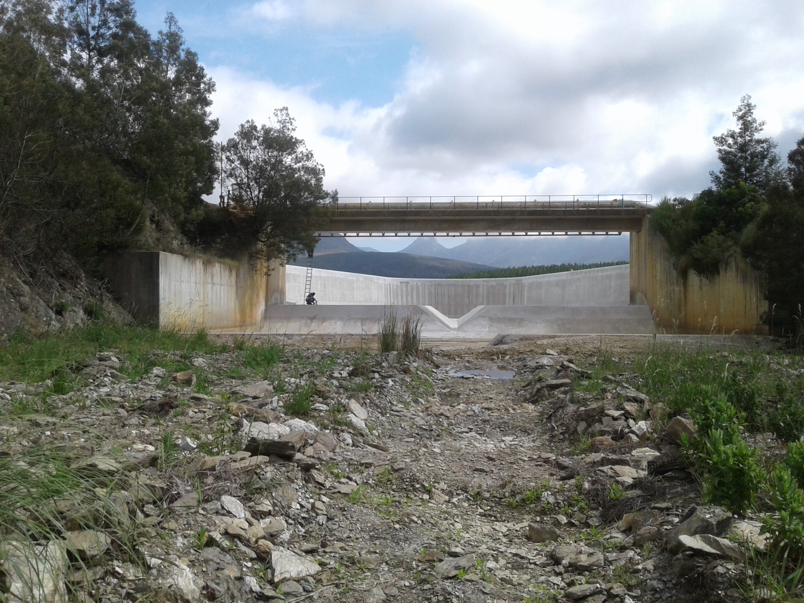
| The existing Garden Route Dam spillway was only 25 m wide. | 1.75 MB | Download | |
 Preview Preview | The rock of the channel in the centre of the duckbill | 1.81 MB | Download |
 Preview Preview | The non-linear spillway extendeding to 80 m | 1.01 MB | Download |
 Preview Preview | The foundation underneath the new spillway sill | 1.26 MB | Download |
| Aurecon designs unique duckbill spillway for the raising of Garden Route Dam_approved | 48.5 KB | Download |
A duckbill spillway is a type of non-linear spillway, similar to the more generally-known labyrinth spillway, explains Frank Denys (PrEng, PhD), from the Water Engineering Unit at Aurecon. Aurecon is currently in the process of rebranding as Zutari, after officially announcing the separation of the African business from the Aurecon Group, effective from 1 January 2020.
The main aim is to increase the overflow length such that the spillway or weir can pass more flow for a given overflow depth. This allows for construction of very long spillways, typically four to five times longer than a linear spillway, in a limited area. The existing Garden Route Dam spillway was only 25 m wide. However, the non-linear spillway extended this distance to 80 m by curving the spillway in the upstream direction.
Raising the dam’s water level was originally envisioned to be limited to increasing the overflow sill of the spillway, or installing some form of fusegate system on the spillway. These options were subjected to technical feasibility studies and an environmental impact assessment. The various spillway gate options appeared attractive from a cost-perspective, but undesirable when considering long-term maintenance.
Furthermore, re-evaluation of the dam’s flood hydrology, following large flood events experienced in the recent past, resulted in flood peaks significantly higher than the original dam and the proposed gate options were designed for. The updated hydrology required that the crest of the embankment also had to be raised to ensure its safety. A new spillway concept, with a significantly higher capacity than the previous alternatives, was devised to be able to pass the flood peaks with as low a head as possible to minimise by how much the embankment would need to be raised by.
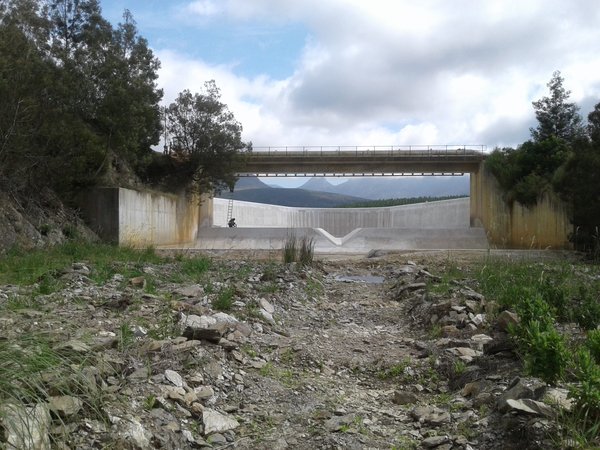
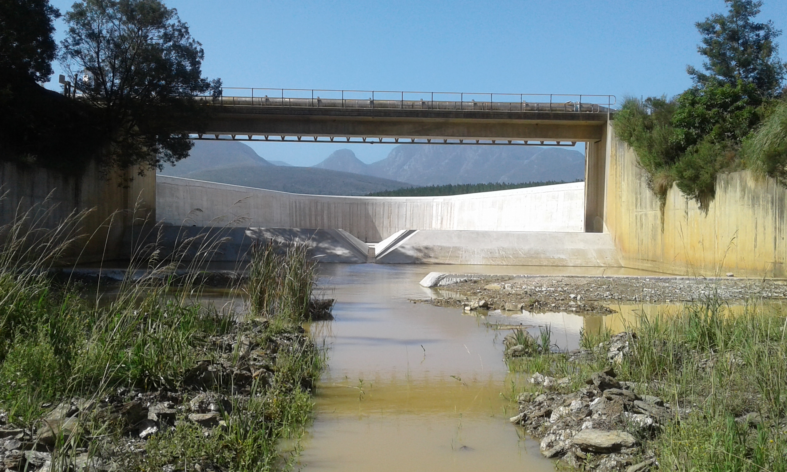
Besides the fact that the spillway needed to have a high discharge capacity, extreme floods also have to pass underneath the road and main water-supply pipeline bridge across the existing spillway, in order to limit the high construction costs of raising this bridge, as well as consequent disruption. The sizeable and relatively flat approach channel allowed for construction of a fixed concrete weir that extends upstream from the existing spillway overflow and training walls. This resulted in the design of a trough or a labyrinth type of weir. Ultimately, the geometry of the site and hydraulic analysis led to the duckbill-shape spillway of the final design.
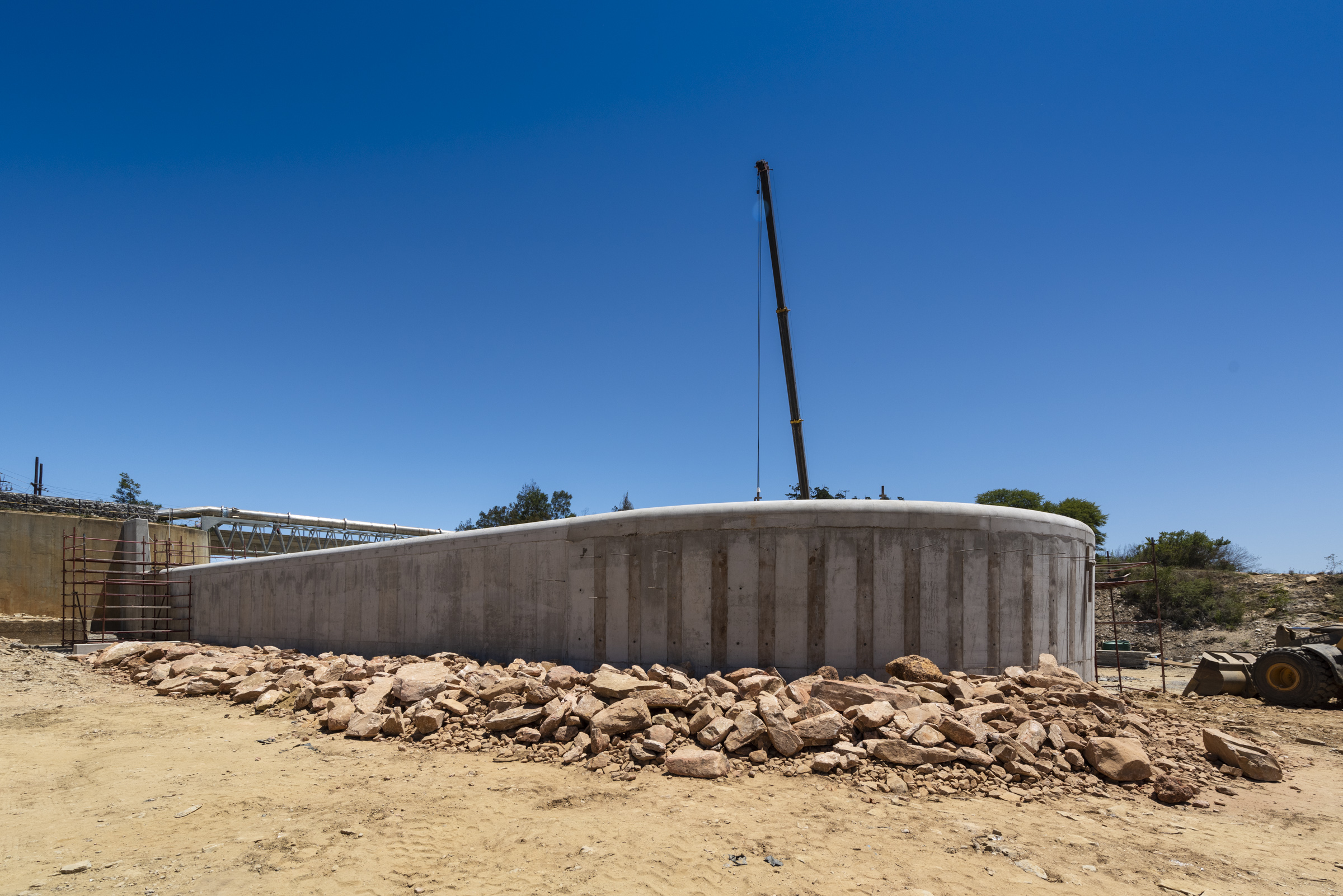
The new sill is a reinforced concrete cantilever structure some 4.9 m tall in places, which is unusual for hydraulic structures of this type as these are normally self-stable by their mass. To enhance the stability, the structure is provided with rockfill on the upstream side of the wall footing, in addition to rock anchors. The rock of the channel in the centre of the duckbill had to be lined with concrete to prevent erosion. This slab also had to be held in place with rock anchors. Further to this, the foundation underneath the new spillway sill was grouted to minimise seepage underneath the wall.
The main dam wall was raised 1.76 m by placing new earthfill on top of the existing embankment. This task had to be achieved in confined spaces, atop high slopes, mostly using available material of suitable quality from the dam basin, and some imported from commercial sources. Selected material was placed as follows: General fill (12500 m3), rip-rap (2500 m3), filter sand (750 m3), and topsoil (2050 m3).
In terms of the spillway, even though the Full Supply Level (FSL) of the dam was raised by 2.5 m, due to the local terrain, the tallest portion of the new spillway wall is 4.9 m tall. A total of 1780 m3 of concrete was used (750 m3 mass concrete, 300 m3 for the walls, 390 m3 for the wall footing, and 340 m3 for the channel) The quantity of steel used was 150 t.
The construction period was seven months, from 13 May to 12 December 2019. However, the various planning stages for the project date back over a decade, with the idea of raising the dam first being investigated as far back as 2004. The main client and dam owner is the George Local Municipality, with project funding from the Regional Bulk Infrastructure Grant.
The 2.5 m raising of the FSL of the dam equates to an increase in the storage capacity of 2.5 million m3 to a total gross storage capacity of 12.5 million m3. “This will add much-needed drought resilience to the water-supply system. Expanding an existing water-supply resource is also preferable to the development of new sites, as it limits the extent of the environmental impact to an already impacted site,” Denys concludes.
Professional team
Client and dam owner: George Local Municipality
Approved Professional Person (Aurecon): Alan Shelly
Dam Engineers (Aurecon): Frank Denys, Chris Seddon, and Wicus du Plessis
Sharples Environmental Services
Construction management (Aurecon): Piet Erasmus, Andre Krige, and Niel van der Westhuizen
Contractor: Khubeka Construction
Sub-Contractors
Earthworks: Amandla Construction
Grouting and anchors: Esor Construction
Concrete supplier: T&T
Reinforcing supplier: RSC
Ivan Steel Fixing
Ends
Notes to the Editor
To download hi-res images for this release, please visit http://media.ngage.co.za and click the Aurecon link to view the company’s press office.
Aurecon Media Contact
Rashree Maharaj
Marketing and Communications
Email: Rashree [dot] maharaj [at] aurecongroup [dot] com
Tel: (012) 427 2000
Web: https://www.aurecongroup.com/
Media Contact
Renay Tandy
NGAGE Public Relations
Phone: (011) 867 7763
Fax: 086 512 3352
Cell: 082 562 5088
Email: renay [at] ngage [dot] co [dot] za
Web: www.ngage.co.za
Browse the NGAGE Media Zone for more client press releases and photographs at http://media.ngage.co.za